The Threshold Logic (ThL) module is essentially a discriminator bank. It takes in the 4 trigger waveforms which are the output of the 4 Finite Impulse Response (FIR) submodules, does its discriminating and forwards the results for further processing by the Peak Search (PS) module. That is, each of the 8 submodules monitors its input and produces a single bit output which indicates whether its input is above a configurable threshold, although two thresholds are used to remove “bouncing” due to noise. The single bit outputs of each of the 8 submodules are collected into a single 8-bit output and then used (along with the 4 trigger waveforms) by the PS module to construct the trigger primitives. The input is a packet of 4 trigger waveform samples received from the FIR module. The output is similarly a packet of 5 words, where the first 4 words are the 4 input trigger waveform samples passed through unaltered from the FIR module, and where the last sample is the (zero-padded) 8 discriminator bits computed by this module. The thresholds will be loaded at the start of running, but may still be changed during running.
There is 1 streaming input, from the FIR module.
- The input contains the following information:
- Trigger waveforms 1-4
- The input is formatted as a 4-channel packetized Avalon-ST stream.
- The input stream includes the following signals (see table 5-1 of the Avalon-ST specification for detailed descriptions of the signal roles):
- 16 bit wide data signal (which is used to carry the 4 inputs in serial)
- 2 bit wide channel-number signal (to specify which of the 4 channels each datum belongs to)
- 1 bit wide valid signal
- 1 bit wide start-of-packet signal
- 1 bit wide end-of-packet signal
- 2 bit wide error signal (which is ignored)
- Packets will be received at a rate of 39.0625 kHz.
- Each packet will consist of exactly 4 data, one from each of the 4 FIR submodules. The Threshold Logic Selector, described below, is used to select which one of the 4 trigger waveforms is used for each of the 8 ThL submodules.
- The input stream includes the following signals (see table 5-1 of the Avalon-ST specification for detailed descriptions of the signal roles):
- The input contains the following information:
- Activation Thresholds Ai: 16 bits/threshold, 1 threshold/submodule, 8 submodules
- Deactivation Thresholds Di: 16 bits/threshold, 1 threshold/submodule, 8 submodules
- Threshold Logic Selectors Si: 2 bits/selector, 1 selector/submodule, 8 submodules
- 100 MHz clock input
- 1 reset input
Note that the thresholds and selectors are set during initialization1 at the start of running and are expected to remain the same during running, but they can be changed at any time if needed.
The Selectors are used by each submodule to select one of the 4 FIR submodules as its input.
There is 1 streaming output, which goes to the the Peak Search module:
- The output contains the following information:
- Trigger waveforms 1-4, passed through this module unaltered
- Discriminator decisions
- The output is formatted as a 5-channel packetized Avalon-ST stream.
- The output stream includes the following signals (see table 5-1 of the Avalon-ST specification for detailed descriptions of the signal roles):
- 16 bit wide data signal (which is used to carry the 5 outputs in serial)
- 3 bit wide channel-number signal (to specify which of the 5 channels each datum belongs to)
- 1 bit wide valid signal
- 1 bit wide start-of-packet signal
- 1 bit wide end-of-packet signal
- Packets will be sent at a rate of 39.0625 kHz, in lockstep with the input packets, with some latency which we will measure during testing of this module.
- Note that the last data signal output is the 8 bit output of this module (the 8 discriminator decisions). Since it is only 8 bits wide, and the output stream is 16 bits wide, the 8 bit output is zero-padded to produce a 16 bit word. The most-significant 8 bits of the data signal are set to 00000000, and the least-significant 8 bits are set to the actual 8 discriminator decisions.
- The output stream includes the following signals (see table 5-1 of the Avalon-ST specification for detailed descriptions of the signal roles):
- The output contains the following information:
This module requires some information to be retained from one time step to the next. It will be stored in internal registers which are not visible or accessible from outside the module. They are mentioned and named here in order to simplify the detailed description of the module’s functionality given below.
- Previous output bi: 8 bits
(Stores the most recent output, which is used to help prevent “bouncing” of the output. See the detailed description below.)
- Previous output bi: 8 bits
The module detects and reports several possible erroneous conditions via a register read. The value read out consists of 16 bits; the most-significant bits are unused.
- Bit 0: Received data outside of a packet
- Bit 1: Received start-of-packet signal during a packet
- Bit 2: Received end-of-packet signal outside of a packet
- Bit 3: Duplicated channel in a packet
- Bit 4: Missing channel in a packet
- Bit 5: Illegal channel number in input
- Bit 6: Read or write to invalid register address
- Bit 7: Invalid value written to register
- Bit 8: Deactivation threshold is higher than Activation threshold
- Bit 9: Input packets arrived too close together
Brief functional description:
Each submodule is essentially a discriminator
with two thresholds to specify when a trigger
waveform goes above a threshold in a way that
avoids bouncing. The output is used by the
Peak Search
module to construct a set of trigger primitives, specifically
to define the peak search window,
report the peak timestamp and peak amplitude,
and construct the
“trigger word”, which is used to make the final
L1 trigger decision in the
Trigger Logic (TrL)
module. There are 8
threshold pairs
used in the discriminators: 8 activation
thresholds and 8 deactivation thresholds, one
for each submodule. This prevents “bouncing”,
or rapid switching of the outputs between 0 and
1, due to noise in the input.Each of the 8 bits in the output is determined
by comparing the input to one
Activation/Deactivation threshold pair, one
selector, and one previous-output bit. The
process for producing an output bit
is identical in each submodule and runs in
parallel, so we will describe the process for
computing only one of the output bits. An
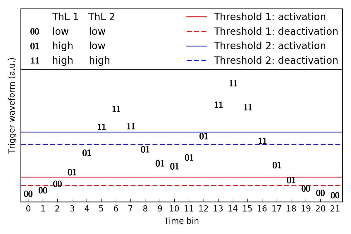
example is given in Figure 1 where we have a
pileup event (two events which occur very
closely in time such that they overlap). We
will report on two different ThL submodule
results, ThL1 and ThL2, both of which consider
this trigger waveform as input. Thus, we will
detail both outputs on the figure.The algorithm is as follows:
- If the trigger waveform is below the deactivation threshold, the output bit will be 0
- If the trigger waveform is between the two thresholds, the output bit will be the same as the previous output
- If the trigger waveform is above the activation threshold, the output bit will be 1
Figure 1 (below) shows the output of two
discriminators for a given trigger waveform
input. The markers on the plot show the output
bits in each time bin. This is an interesting
example because it has two peaks in it. Both
ThL1 and ThL2 go above their thresholds at some
point, but because of the value of the
thresholds, ThL1 goes back down to 0 for a
while (reports 2 peaks) while ThL2 stays high
for the duration of both peaks. Note the inputs
that fall between an activation and
deactivation threshold (e.g. time bins 12 and
16) — the output value then depends on the
previous output value.
Figure 1
More detailed description (including data transfer information):
Step-by-step:
- Wait for an input packet to arrive from the FIR modules. Recall that the packet consists of 4 trigger waveform samples, one after another, so steps 2-4 below will be repeated 4 times.
-
When each datum of the input packet is
received, the 8 submodules run in
parallel to compute the output (perform
the discrimination). The $i$th
submodule computes one of the 8 bits as
follows. The computation of the $i$th
output bit uses- Data Input:
- the input channel number $C$ from the current input datum,
- the input value $V$ from the current input datum.
- Configuration Inputs:
- the $i$th Threshold Logic Selector $S_i$,
- the $i$th Activation Threshold $A_i$,
- the $i$th Deactivation Threshold $D_i$.
- Module determined:
- the current value $b_i$ of the $i$th bit in the “previous output” internal register.
Then, the $i$th computed bit is given
by the logical expression:
\[(b_i \land ((C \neq S_i) \lor (V > D_i))) \lor ((C == S_i) \land (V > A_i) \land (V > D_i)),\]
where $\land$ is logical AND, and
$\lor$ is logical OR.Store the $i$th computed bit into the
$i$th bit of the “previous output”
internal register, replacing the
previous value.Note that, when the channel number
\(C\) does not match the \(i\)th
Selector \(S_i\), the new value of the
\(i\)th bit will be the same as the old
value \(b_i\). That is, each bit only
actually changes once per input packet,
when the channel number matches the
Selector. - Data Input:
- Send the most-recently received input datum
as output to the PS module. Set the
valid bit,
start-of-packet
bit, data bits,
and
3 channel-number bits
exactly like the input, but do not set
the end-of-packet
bit signal. This way, the
input is passed through unchanged, except
that one additional datum can be added to
the packet. - Unless the input contains the end-of-packet
signal, return to step 2, waiting for the
next datum of the input packet. - After the last (fourth) input datum has arrived (i.e., the input contains the end-of-packet signal), do the following on 2 consecutive clock cycles:
- Set the 8 most-significant data bits
to 00000000 and set the 8 least-significant data bits
to the value stored in the “previous output” internal register.
Concurrently, set the 3 channel-number bits to 100,
set the valid bit and set the
end-of-packet bit. - Unset the valid bit
and the end-of-packet bit.
- Set the 8 most-significant data bits
Reset Signal:
When the reset input is asserted,
- Set all the Thresholds to zero
- Set all the Selectors to zero
- Set the “previous output” internal register to all zeros
- Reset the subsystem monitoring the input packets and checking for errors
- Set all the error bits to zero
When the reset input is deasserted,
- Go back to Step 1 of the detailed description
- See here for the overall testing plan.